555 Timer Internal Schematic / 555 Timer Teardown Inside The World S Most Popular Ic - The 555 timer ic is an integrated circuit (chip) used in a variety of timer, delay, pulse generation, and oscillator applications.
byAdmin•
0
555 Timer Internal Schematic / 555 Timer Teardown Inside The World S Most Popular Ic - The 555 timer ic is an integrated circuit (chip) used in a variety of timer, delay, pulse generation, and oscillator applications.. So, before using your ic in any project, make sure that your ic is good or bad by testing it. This simple 555 ic testing circuit can be used to test your entire 555 timer ic collection. Start date nov 11, 2009; The voltage must be at least 4.5v and no greater than 15v. The 555 timer has two basic operational modes:
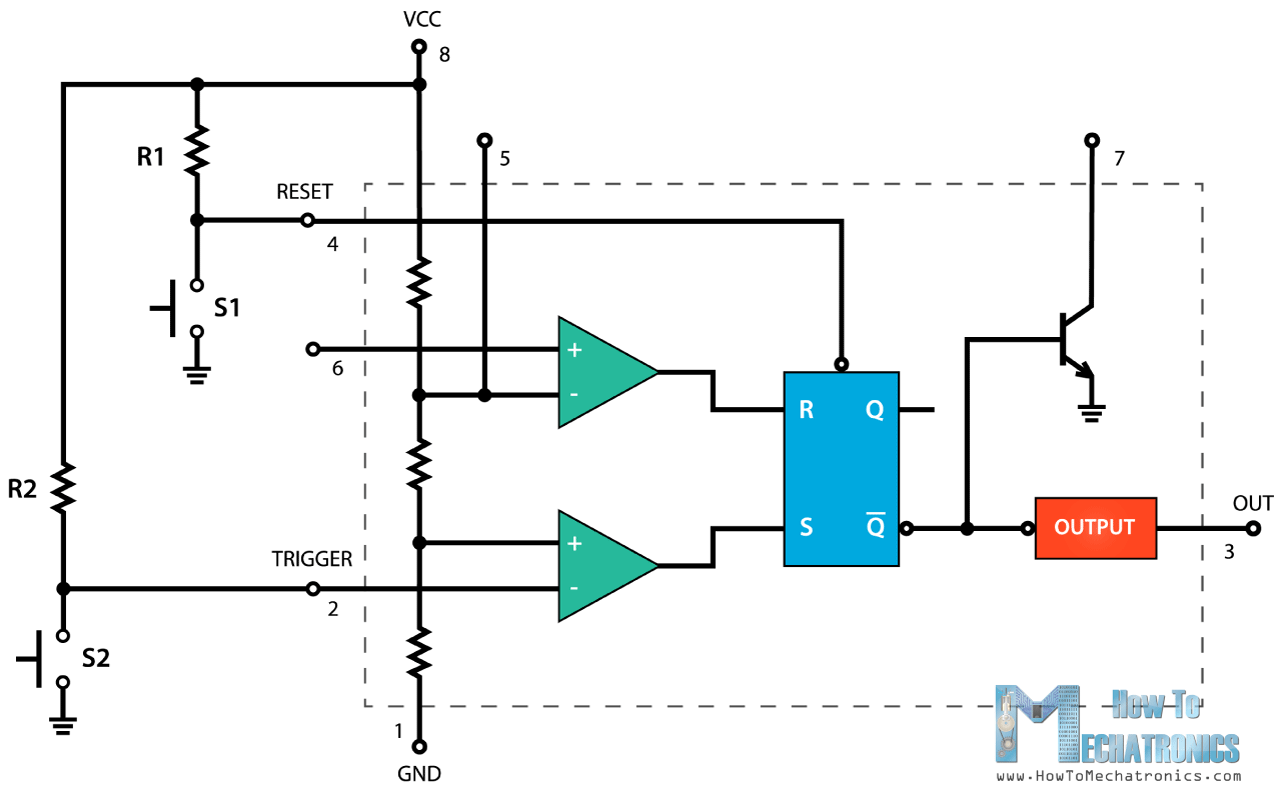
The 555 timer is a chip that can be us… Using the 555 timer ic in special or unusual circuits. Since the application is built on cloud, it gives the convenience of mobility and portability. The image shown below represents the internal schematic of a standard ic 555. The internal block diagram and schematic of the 555 timer are highlighted with the same color across all three drawings to clarify how the chip is implemented:2.
Comparing 555 Pwm Circuits General Electronics Arduino Forum from aws1.discourse-cdn.com An external capacitor is repeatedly charged and discharged to produce the oscillation. 555 timer internal circuit operation. In this video, i've explained 555 timer ic with the pin diagram and the internal circuit diagram. In this section, we will see the working of each internal component of the 555 timer ic. It is very common and mostly used ic in various circuits and schematics. Using the 555 timer ic in special or unusual circuits. In 2017, it was said over a billion 555 timers are produced. The diagram below illustrates the internal operation of the 555 timer used as an oscillator.
The 555 timer ic is an integrated circuit (chip) used in a variety of timer, delay, pulse generation, and oscillator applications.
We can see that it us made up of 21 transistors, 4 diodes, and 15 resistors. The 555 timer internal circuit diagram is shown below: The circuit latches in either the q state or its refer block diagram of 555 timer ic given above: We have seen in the last few tutorials that the 555 timer can be configured with externally connected components as multivibrators, oscillators and timers, with timing intervals ranging from a few microseconds to many hours. Internal diagram of 555 timer ic. The standard 555 timer ic is made of 2 diodes. 555 timer internal schematic questions thread starter jearls74; Steps to make a simple led flashing circuit. It can operate in both astable and monostable modes. As its wide range of usability and compatibility, also its more range of operating voltage and various other feature makes it ideal for wider use. Additional • timing from microseconds through hours terminals are provided for triggering or resetting if • operates in both astable and monostable modes desired. 555 timer internal circuit diagram. Lm555 timer 1 features 3 description the lm555 is a highly stable device for generating 1• direct replacement for se555/ne555 accurate time delays or oscillation.
Lm555 timer 1 features 3 description the lm555 is a highly stable device for generating 1• direct replacement for se555/ne555 accurate time delays or oscillation. The ic 556 and ic 558 are 14 pins dual timer and 16 pin quad timer versions of the ic 555 respectively. An external capacitor is repeatedly charged and discharged to produce the oscillation. The 555 timer has two basic operational modes: This is the pin which connects to the dc voltage to power the 555 chip.
Another 555 Timer Question Scraching My Head On It from ecee.colorado.edu 555 timer helpers schematic the addition of a capacitor to the trigger will not work for short output pulses as there is also a short delay in the recovery of the trigger terminal voltage. There are a lot of applications of this ic, mostly used as vibrators like, astable multivibrator, monostable multivibrator, and bistable multivibrator. The 555 is also very versatile, and can be used. In this video, i've explained 555 timer ic with the pin diagram and the internal circuit diagram. If a 10uf timing capacitor is used, calculate the value of the resistor required to produce a minimum output time delay of 500ms. This tutorial provides sample circuits to set up a 555 timer in monostable, astable, and bistable modes as well as an in depth discussion of how the 555 timer works and how to choose components to use with it. An external capacitor is repeatedly charged and discharged to produce the oscillation. In 2017, it was said over a billion 555 timers are produced.
The internal circuit of this 555 timer consists of comparators, flipflops, transistors, resistors, and output stages.
In this article, we cover the following information about 555 timer ic. The 555 tester circuit will rapidly tell you. 500ms is the same as saying 0.5s so by rearranging the formula above, we get the calculated value for the resistor, r as: As its wide range of usability and compatibility, also its more range of operating voltage and various other feature makes it ideal for wider use. The 555 timer internal circuit diagram is shown below: If a 10uf timing capacitor is used, calculate the value of the resistor required to produce a minimum output time delay of 500ms. 555 internal circuit consists of three series 5k resistors connected between the vcc and gnd. 555 timer helpers schematic the addition of a capacitor to the trigger will not work for short output pulses as there is also a short delay in the recovery of the trigger terminal voltage. A monostable 555 timer is required to produce a time delay within a circuit. This is the pin which connects to the dc voltage to power the 555 chip. This simple 555 ic testing circuit can be used to test your entire 555 timer ic collection. The 555 timer has two basic operational modes: In this video, the brief introduction to the 555 timer ic has been given and the pin diagram (of 8 pin dip 555 ic) and the internal block diagram of the 555.
We can see that it us made up of 21 transistors, 4 diodes, and 15 resistors. The 555 is also very versatile, and can be used. Timing can be anywhere from microseconds to hours. Start date nov 11, 2009; In 2017, it was said over a billion 555 timers are produced.
555 Timer Ic Working Principle Block Diagram Circuit Schematics from howtomechatronics.com Monostable 555 timer circuits will automatically trigger and start a timing cycle when power is applied to the circuit. The ic 555 basically a timer ic. In this section, we will see the working of each internal component of the 555 timer ic. With this information you will learn how how the 555 works and will have the experience to build some of the circuits below. No external triggering is required in astable mode, it automatically interchange its two states on a particular interval, hence generates a rectangular waveform. An external capacitor is repeatedly charged and discharged to produce the oscillation. This article covers every basic aspect of 555 timer ic. The 555 tester circuit will rapidly tell you.
It can operate in both astable and monostable modes.
The timer's internal circuitry is largely responsible for this triggering but it is also caused stray or installed capacitance at the trigger input of the timer. Lm555 timer 1 features 3 description the lm555 is a highly stable device for generating 1• direct replacement for se555/ne555 accurate time delays or oscillation. 555 is configured in astable mode of operation. It is very common and mostly used ic in various circuits and schematics. Additional • timing from microseconds through hours terminals are provided for triggering or resetting if • operates in both astable and monostable modes desired. As its wide range of usability and compatibility, also its more range of operating voltage and various other feature makes it ideal for wider use. In this video, i've explained 555 timer ic with the pin diagram and the internal circuit diagram. If a 10uf timing capacitor is used, calculate the value of the resistor required to produce a minimum output time delay of 500ms. The 555 is also very versatile, and can be used. In this video, the brief introduction to the 555 timer ic has been given and the pin diagram (of 8 pin dip 555 ic) and the internal block diagram of the 555. This tutorial covers different aspects of 555 timer ic and explains its working in The second 555 timer helper will extend the timers output duration without having to use large values of r1 and/or c1. Octopart is the preferred search engine for electronic parts.
500ms is the same as saying 05s so by rearranging the formula above, we get the calculated value for the resistor, r as: 555 timer schematic. You can find here some circuits based on 5555 ic.